
Current and Voltage Clamp switching for the MultiClamp 700
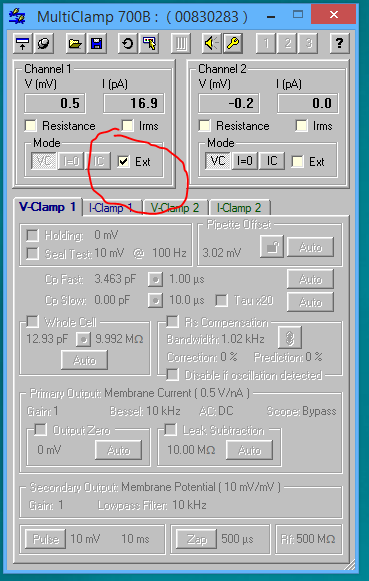
jClamp can do real time switching between current clamp and voltage clamp in protocol files when an Axon 700B Multiclamp amplifier is connected. The amp must be in external mode.
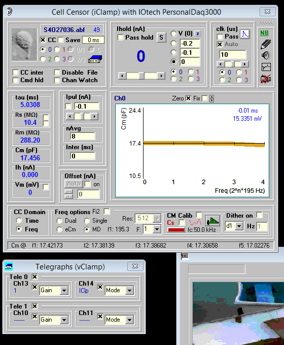
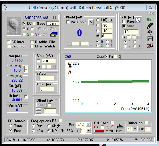
You will need to setup current and voltage clamp in CC window to make sure things are working first in each mode separately. To measure Cm you will need calibration files for IC and VC, and the file names need to be placed in the ini file. Everything I talk about here was done with an electrical model at the headstage. Real cells require careful interpretations due to nonlinearities. To balance out stray capacitance use the MD feature under Frequency domain. IC Cm is not as good as good as VC because stray capacitance is balanced out with positive feedback and is achieved when the system is near oscillation. Of course, you should back off compensation a bit so as not to kill cells with these oscillations. You should have multiclamp telegraphs working in jClamp so gains and mode can be registered by jClamp.
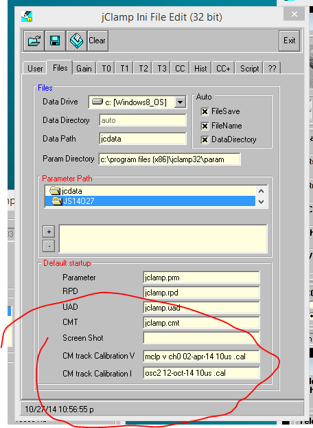
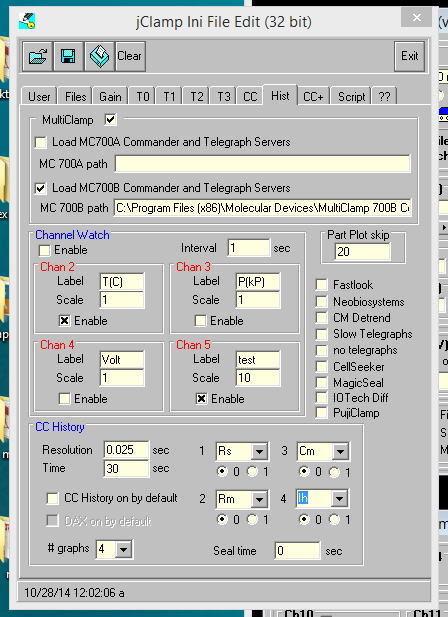
Multiclamp must be selected in the jClamp ini file.
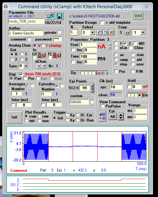
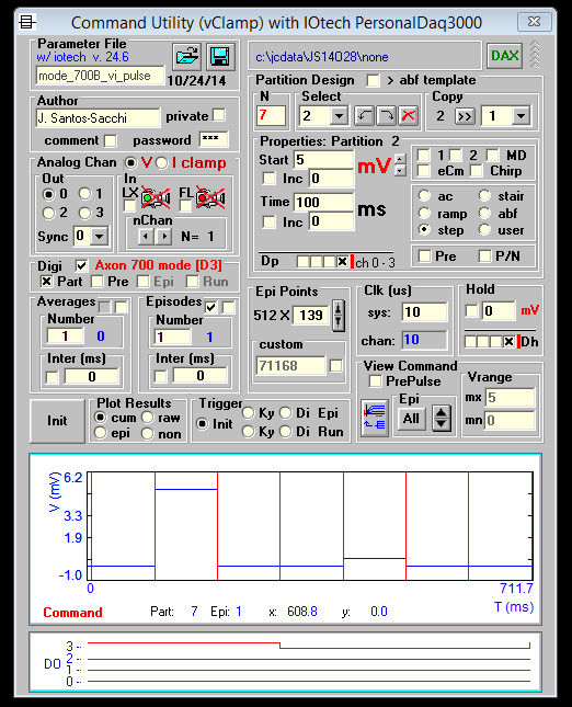
Building a command starts with a voltage clamp protocol. Select Axon 700 mode [D3] and Part in the Digital section. Digital output 3 is used to switch between IC (off) and VC (on). Trace 3 of the digital protocol is red. By setting digital 3 for any partition, you can make that partition VC or IC. You can select a partition from the drop down box or move the mouse onto red vertical line partition demarcations in the command plot. When a partition is in VC, mV is displayed, and nA is displayed for IC. Values are in nA for IC and in mV for VC partitions. Since the command plot shows both nA and mV the view may appear odd. Select a partition to view the magnitude of that partition command.
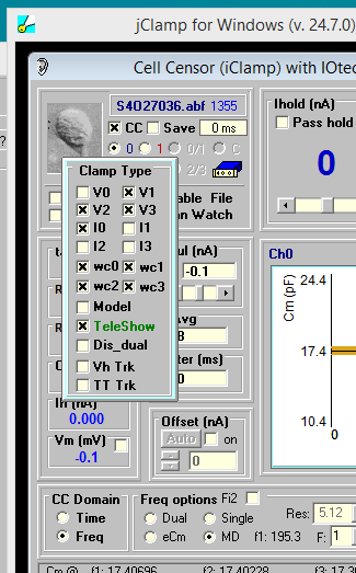
To switch between VC and IC in CC when in ext mode in multiclamp, select V0 or I0 (Channel 0 amplifier).